Background : Material removal processes like milling were developed
for metals and are found not to be particularly suitable for long-fiber reinforced composites
(e.g., Carbon-Fiber Reinforced Plastics – CFRP in particular). Among the most significant
problems encountered are (i) the generation of delamination defects (i.e., inter-laminar cracks that are
difficult to identify), and (ii) a highly inefficient cutting process due to extensive wear of the milling tools.
Water-jet cutting and laser machining were among the non-conventional processes tested by industrials on
these materials. Water-jet cutting uses abrasive particles to produce highly efficient
cuts, but it has the drawback of exposing the composite material to moisture. As for laser
machining technology, it is slow and remains quite expensive at the present time.
Challenge : To find alternative material removal processes that can
outperform those currently employed for CFRP.
Solution : Use of powder blasting micromachining process for direct abrasive etching
of CFRP or, as an alternative, in combination with a photolithography mask.
Result : Exploiting one of the weaknesses of composite materials – particle
erosion, a pressurized jet of air mixed with abrasive particles (alumina powder with an
average particle size of 50 μm) is directed towards the CFRP surface,
and material is removed through the powder blasting process. It is found that this micromachining process is
highly efficient and cost-effective when compared with existing methods, achieving material
removal rates several times faster than laser machining. Further investigation through
high-resolution X-Ray Computed Tomography (2.75 μm resolution) showed no trace of delamination nor micro-cracks.
Typically, the powder blasting process is employed with a polymer mask on thin sheets of material.
It was found that higher material removal rates and clear entry points could be achieved through
direct powder blasting, paving the way towards 3-dimensional machining. However, the etching process
is not constant throughout the material. This is primarily due to the structure of the material
(anisotropy) but also to the lack of control on the powder jet. Work is underway in improving
the process repetability and first applications are being developed.
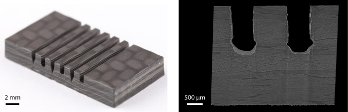
Grooves of approximately 0.8 mm width and 2 mm depth machined by direct
powder blasting in a 3.2 mm thick CFRP plate. The picture on the right is an X-Ray Computed Tomography
cross-sectional view of a powder blasted CFRP sample showing the grooves geometry.
Neither delamination nor micro-cracks were observed.
B. Optoelectronic metrology instrument
Industry : Mechanical watchmaking
Background : In a mechanical watch, the energy is provided by a wound
spring (mainspring) through a set of gears which ends in a mechanism known as the
escapement. The purpose of the escapement is to interrupt the
movement of the wheels at regular intervals and to convert the rotation
of the wheel train into controlled and regular steps. This is ensured by the
regulating organ (i.e., the oscillator of the mechanical watch), consisting
of a hairspring and a balance wheel, which oscillates at a relatively
accurate frequency.
Acoustics is the traditional method used by watchmakers to
measure the watch rate and to estimate the oscillation amplitude of the
balance wheel. Listening to the ticking of a watch is a very simple way to
characterize the mechanism, but it suffers from several limitations
inherent to the measuring principle. In particular, the free oscillation of
the regulating organ provides crucial information that can’t be measured
acoustically. Indeed, in the absence of the escapement, no ticking occurs …
Challenge : Watchmaking laboratories are interested in innovative metrology solutions
for the characterization of their mechanical watches (e.g., optical methods as an alternative to acoustics).
Solution : Characterization through optical tracking of the balance rim. Video analysis
(image correlation) is performed with a high-speed CMOS camera.
Result : Development of an optoelectronic watch timing machine that
enables watch-testing laboratories to perform comprehensive analyses of
their mechanical movements in all measuring positions. The instrument
performs real-time tracking of the balance wheel. A graphical user
interface gives access to the instantaneous watch rate (oscillation
frequency), to the amplitude, to the isochronism, and to the quality
factor.
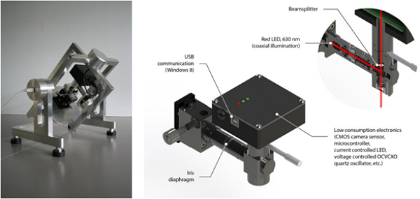
Optoelectronic watch timing platform.
The illustration is a 3D view of the optical system
(CMOS camera and associated optical elements).
C. MEMS: Silicon microactuators with flexure bearings
Industry : Hard-Disk Drive
Background : In a Hard-Disk Drive (HDD), the Read/Write
head is brought over the storage media by a coil-driven
support arm. The skew angle (angle between the longitudinal axis of the
support arm and the recording track), varies with the radial position of the
heads on the disk. Large variations in the skew angle, reaching almost
30° (+/-15°) for typical 3.5-in drives, diminish the performance
of HDDs.
Challenge : The Storage Research Consortium (SRC, Japan) was interested in an integrated
MEMS microactuator that could compensate for the skew angle, while showing excellent dynamic performance.
Solution : Design of silicon-based rotary stepper micromotors with folded-beam suspensions (i.e., flexure
beams).
Result : Integrated micromotors have been designed, fabricated, and extensively characterized.
Several micromachining processes have been used, among which Silicon-On-Insulator (SOI) technology and Vertical
trench isolation technology. Our work has also addressed theoretical modelling of flexure pivot mechanisms, with
comprehensive analytical modelling based on strength of materials.
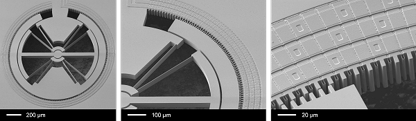
Scanning Electron Micrographs of a 3-phase electrostatic stepper micromotor
in silicon.
The device was fabricated by vertical trench isolation technology.
Left: Animation showing the deformation of a rotary folded-beam suspension (FEA simulation).
Right: Video of a rotary stepper micromotor fabricated by vertical trench isolation technology.